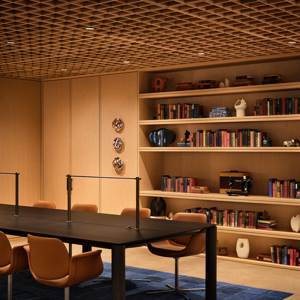
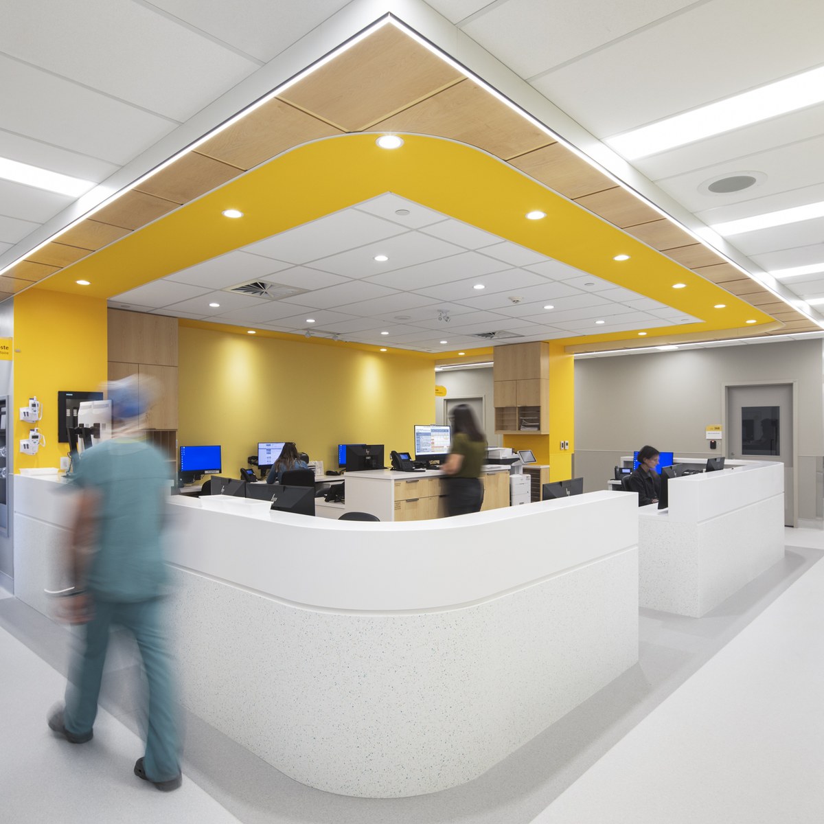
C Series Recognized for Addressing Key Engineering and Facility Challenges

DMF Lighting’s C Series commercial downlights have earned recognition as a bronze winner in the 2026 Consulting-Specifying Engineer (CSE) Product of the Year awards, an annual program that highlights innovative solutions shaping the future of non-residential building design and construction.
Selected by CSE readers, the awards honor products that demonstrate technological advancement, industry value and market impact. The winners underscore the importance of technologies helping engineers and building owners address key priorities such as energy efficiency, electrification, resiliency, safety and digitalization.
DMF’s award-winning C Series 4- and 6-inch commercial downlights stand out for their modular, tool-less design that simplifies installation, maintenance and future upgrades. The system combines housing, light engine modules and trims in a plug-and-play platform engineered to balance performance, serviceability and cost efficiency.
A key feature of the C Series is its integrated driver design, which allows modules to be replaced from below the ceiling without requiring any ceiling modifications. This approach helps reduce maintenance time and costs while enabling touch-safe onsite modifications. The light engine modules are available with an adjustable lumen output switch (1,000, 1,500 or 2,000 lumens) or fixed output option, providing flexibility across a range of ceiling heights and application requirements.
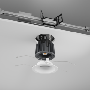
In addition, the trims incorporate an integrated mixing chamber and wide-angle light distribution to maximize efficiency and deliver consistent illumination.
The recognition underscores DMF’s commitment to developing practical, high-performance lighting solutions that help engineers, specifiers and project teams create the next generation of commercial buildings.
Learn more about the award-winning C Series by watching the product video. You can also download the Winners eBook for a complete look at the 2026 Product of the Year recipients.
The Optical Challenge of Small-Aperture Lighting

Small-aperture lighting delivers the clean, minimal aesthetic many architectural interiors demand, but achieving high performance in a 1-inch downlight presents unique optical challenges. One of the least discussed is Color Over Angle (CoA), a phenomenon that can cause the perceived color of light to change as the viewing angle shifts.
For lighting designers, architects, and specifiers, understanding CoA is increasingly important when selecting ultra-small-aperture downlights, particularly in applications where consistent color, precise beam control, and low glare are critical.
CoA refers to variations in correlated color temperature (CCT) and chromaticity as the viewing angle of light from a single luminaire changes. An LED source may appear, for example, 3000K when viewed on axis (0°) but shift toward 2700K—or exhibit a visible blue or amber tint—when viewed off axis. In simpler terms, CoA describes how consistently a fixture maintains its color as the viewing angle changes across its beam.
CoA is different from fixture-to-fixture color consistency, which is influenced by LED binning. CoA is a within-fixture phenomenon: the same downlight can produce different perceived colors depending on where the observer or illuminated surface is positioned relative to the beam’s optical axis.
The effect can appear in several ways, including a visible color ring at the edge of a beam, a cool-blue core surrounded by a warmer halo, or a perceptible color shift as someone moves beneath a fixture. With adjustable or gimbal downlights, it can also appear as a perceived color mismatch between adjacent fixtures aimed at different angles.

Pictured: Example of poor CoA performance, with the bottom-right portion of the beam appearing significantly more yellow/amber than the rest of the beam.
For designers, these shifts may be subtle—or they may become highly visible depending on the application.
CoA can occur in many types of lighting fixtures, but ultra-small-aperture recessed fixtures can be particularly susceptible because the LED, optics, and other components must all fit within a highly constrained space. Fixtures with a true 1-inch aperture are also limited by the size of the light-emitting surface (LES) that can be used.
These spatial constraints affect the optical system in several ways.
One-inch fixtures typically need to package the LED, optics, and lens arrays within a very short distance, often close to the fixture’s exit aperture. This leaves little room for the light to blend before exiting the fixture.
As a result, angular color non-uniformity in the LED source can be projected from the fixture with limited optical mixing. Larger aperture fixtures typically provide greater distance and surface area for optical mixing, making these variations less noticeable in the resulting beam.
The overall diameter of the optics is also smaller, particularly in fixtures designed to maintain an overall diameter close to their 1-inch aperture. This constrained diameter greatly reduces the surface area available within the optical system to redirect and homogenize light rays from different points on the LED package.
Most white LEDs produce light by pairing a blue LED die with a yellow or yellow-and-red phosphor. Light emitted near normal (0°) to the die travels through a shorter effective path in the phosphor than light emitted at more oblique angles.
This difference in optical path length changes the balance between converted and unconverted blue light as a function of angle. In general, light traveling through a greater effective phosphor path undergoes more conversion, altering the spectral balance of the emitted light. This angular effect is common in phosphor-converted LEDs and can become more noticeable when combined with the small optical packages and limited mixing distances of 1-inch fixtures.
Narrow optics, typically in the sub-30° range, can make angular color shifts more visually apparent by concentrating the light into a smaller area and increasing intensity and color contrast. This can make color variation more noticeable than with a wide-flood optic, where the same angular differences are distributed across a larger area.
There is an important distinction between a fixture with a 1-inch aperture and a fixture whose overall diameter is 1 inch.
One approach to creating a 1-inch aperture is to use a pinhole trim that reduces a larger fixture opening to a 1-inch visible aperture. This design allows for a larger fixture and optical system with greater mixing distance, similar to what is found in traditionally sized downlights.
But that approach can involve trade-offs.
A larger fixture may require a larger trim flange, which can diminish the minimal aesthetic appeal of a 1-inch aperture. Components of the fixture may also be inaccessible after installation, creating significant challenges for maintenance, service, or future design changes.
A true 1-inch fixture, by contrast, maintains the minimal form factor of the 1-inch aperture throughout the fixture itself. The trade-off is that the LED, optics, and other components must be engineered within a much more constrained space. This creates greater optical challenges, including the potential for increased CoA, while preserving the clean architectural appearance and compact form factor that make small-aperture lighting desirable.
Fixture manufacturers must carefully balance the competing demands of output, beam uniformity, glare control, and aperture size when designing ultra-small-aperture fixtures. Several strategies can help reduce CoA.
Remote phosphor design separates the phosphor layer from the LED die and can help produce more uniform color. Remote-phosphor designs can also offer benefits related to thermal management, efficiency, and LED longevity, depending on the implementation. However, the technology requires additional physical space, making it better suited to larger fixtures, such as linear lighting and soft panels used in film and television. It is generally impractical for ultra-small-aperture recessed fixtures.
Color mixing chambers add distance or dedicated mixing space within the optical system, allowing light to blend more uniformly before exiting the fixture. This approach becomes increasingly difficult as available space decreases, particularly in true 1-inch fixtures. Additional mixing can also come at the expense of lumen output and optical efficiency—an especially important consideration when the limited LES size of a 1-inch fixture already places a premium on maintaining output.
Diffusion elements are another common strategy for improving color uniformity. Microstructured films or textures can be incorporated into optical elements to introduce controlled scattering, helping blend light from different areas of the LED source and reduce visible color variation. The trade-off is some loss in lumen output and optical efficiency, although that loss can be modest enough to justify the improvement in color uniformity.
For a true 1-inch fixture, the challenge is finding the right balance: high output, beam control, glare management, and color uniformity—all within an extremely small optical envelope.
CoA is not a widely discussed, tested, or reported metric for lighting fixtures, even among top-tier architectural-grade products. Testing CoA variation typically requires advanced photometric equipment, such as a goniophotometer paired with a spectroradiometer, to measure CCT and chromaticity at multiple angles across the beam rather than at a single normal (0°) position. Depending on the equipment and measurement protocol, this type of testing can take multiple hours to complete.
Lighting manufacturers also have not traditionally reported CoA data on specification sheets or in photometric reports. Traditional apertures in the 3-inch and larger range generally experience less severe color-over-angle variation than ultra-small-aperture fixtures, while 1-inch apertures can amplify the effect significantly.
For this reason, visual evaluation of a physical fixture sample remains a practical and effective way to assess whether any CoA variation falls within an acceptable range. The intended application should also be considered. General-purpose downlighting, where individual beams blend smoothly, may be more forgiving of CoA variation than accent lighting applications where fixtures illuminate artwork or other highly visible surfaces.
DMF’s True 1 downlight is a true 1-inch-aperture fixture that employs a unique optical stack to balance powerful output, extremely low glare, and excellent angular color uniformity.
The True 1 three-stage optical stack utilizes non-imaging optics to create a precise cross beam focus that is highly effective at mitigating glare at the fixture’s exit aperture. The final optical element in the stack features a precisely engineered level of microstructure diffusion that softens and diffuses variations in the source image.
Together, these optical approaches allow the fixture to balance high output, low glare, and uniform color over angle within a minimal 1-inch form factor. The result is a small aperture downlight designed not simply around what can fit into a 1-inch opening, but around what can be achieved optically within it, while also delivering installation simplicity and long-term serviceability.
The appeal of a 1-inch downlight is easy to understand: less visual presence, cleaner ceilings, and the ability to deliver architectural illumination without allowing the fixture itself to dominate the space.
But achieving that minimal aesthetic without compromising performance requires more than simply making a fixture smaller.
It requires thoughtful optical engineering at every stage—from the LED and mixing strategy to beam control, glare management, and color consistency.
That’s the real challenge of a true 1-inch downlight and where optical design makes the difference.

Pictured: DMF’s True 1 optical stack and resulting cross beam focus.
Why Optics Matter More Than Ever in the Age of Small-Aperture Downlighting
Over the past decade, architectural lighting has experienced a significant shift toward smaller and smaller luminaire apertures. Once, 4-inch and 6-inch recessed downlights dominated commercial and residential projects alike. Today, however, designers routinely specify 2-inch fixtures, and increasingly, apertures below 2 inches are becoming viable options for high-end architectural applications.
The driving force behind this trend is clear. Architects and interior designers continue to pursue cleaner ceiling planes, minimalist aesthetics and environments where lighting quietly supports the architecture rather than becoming a visual focal point. Advances in LED technology have enabled this evolution, allowing compact fixtures to deliver light output levels that would have been impossible only a few years ago.
Yet while smaller apertures create more elegant ceilings, they also introduce a fundamental challenge: glare.
As fixture apertures shrink, the same amount of light must be delivered through a much smaller opening. The result is higher luminance at the aperture and a dramatically increased potential for visual discomfort. This reality has elevated optical engineering from a secondary design consideration to one of the most critical aspects of downlight development.
Today, the success of a small-aperture downlight depends not simply on its lumen output or efficiency, but on the sophistication of the optical system behind it.
At first glance, it might seem intuitive that smaller fixtures would naturally be less noticeable and therefore more comfortable. In reality, the opposite can often be true.
Consider two fixtures producing the same lumen output. If one distributes that light across a large aperture and the other emits it through an aperture half the size, the smaller fixture will exhibit significantly higher luminance at its opening. To the human eye, that concentrated brightness can become distracting or even uncomfortable.
This challenge becomes especially apparent in environments where occupants spend significant amounts of time looking across a room rather than directly downward. Hospitality spaces, residences, healthcare facilities and workplaces all place occupants in positions where ceiling fixtures frequently enter their field of view.
Without careful optical control, a small aperture can appear as an intensely bright point source that attracts attention and degrades visual comfort.
The challenge for manufacturers is therefore twofold: maintain the performance expectations of modern lighting while simultaneously minimizing source visibility and glare.
LEDs have revolutionized lighting because of their efficiency, longevity and compact size. However, the light produced directly from an LED source is rarely suitable for architectural applications.
In its natural state, an LED emits light according to what is known as a Lambertian distribution. This means light radiates broadly in nearly every direction with relatively uniform intensity.
While this characteristic may be advantageous from a manufacturing perspective, it creates several problems when incorporated into a recessed downlight.
Without optical control, light can spill into the ceiling cavity, strike fixture trims, illuminate surrounding surfaces at unintended angles and expose the bright LED source directly to room occupants. The result is wasted light, reduced efficiency and increased glare.
This is where optics become indispensable.
Optical systems transform raw LED output into useful illumination. Through carefully engineered components, designers can shape beam distributions, improve efficiency, conceal the source and create visually comfortable environments.
In many respects, optics serve as the bridge between an LED’s technical capability and the occupant’s visual experience.
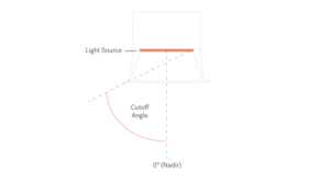
Figure 1 – A diagram showing the cutoff angle of a recessed downlight.
Among the many metrics used to evaluate downlight performance, cutoff angle is one of the most important when discussing glare.
A cutoff angle describes the point at which the light source is no longer visible to an observer. Above this angle, the optical system successfully shields the source from view. Below it, the source becomes progressively more visible.
The concept may seem simple, but its impact on visual comfort is profound.
A fixture with a narrow cutoff angle limits the number of viewing positions from which occupants can see the brightest portions of the luminaire. Consequently, the fixture appears more comfortable and less visually intrusive.
In residential living rooms, hotel guestrooms, restaurants and healthcare facilities, where occupants frequently sit or recline, narrow cutoff angles are often critical. People naturally view ceilings from shallow sightlines, increasing the likelihood of seeing directly into fixture apertures.
By contrast, in spaces with higher ceilings and more upright occupant positions, such as commercial lobbies or atriums, wider cutoff angles may be acceptable.
As apertures continue shrinking, achieving meaningful cutoff becomes increasingly difficult because there is less physical space available to shield the source. This challenge places greater importance on sophisticated optical design.
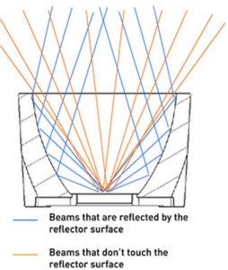
Figure 2 – An example of light beams that escape a reflector without hitting a surface, causing unwanted glare.
Reflectors represent one of the oldest and most familiar forms of optical control in lighting.
The principle is straightforward. Light emitted from the LED source strikes a reflective surface and is redirected toward the intended target area. By adjusting the shape and depth of the reflector, designers can create narrow, medium or wide beam distributions.
Reflectors offer several advantages. They can be highly efficient, produce attractive beam patterns and naturally contribute to glare control by physically recessing the light source.
For decades, deep reflector geometries formed the foundation of architectural downlighting.
However, reflector systems face increasing limitations as apertures shrink.
Effective reflector designs require physical depth. As fixtures become smaller and ceiling plenums become more constrained, the available space for meaningful reflector geometry diminishes. Reflectors also introduce optical losses through absorption and can struggle to capture very wide-angle rays emitted by LED sources.
While reflectors remain important, they are often no longer sufficient on their own for modern small-aperture fixtures.
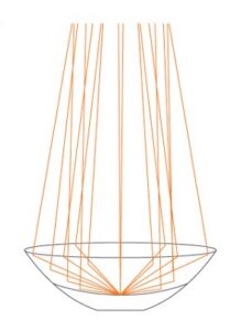
Figure 3 – A diagram of a TIR optic, which concentrates light to a tight narrow beam.
Refractive lenses provide another powerful approach to optical control.
Unlike reflectors, which redirect light through reflection, refractive optics bend light as it passes through materials with different refractive indices. This allows designers to manipulate ray trajectories with exceptional precision.
Among the most common examples are Total Internal Reflection (TIR) lenses. These optics combine refractive and reflective properties within a single element, capturing a large percentage of LED output and directing it into highly controlled beam patterns.
TIR lenses have become especially valuable in compact architectural fixtures because they can deliver precise beam control without requiring deep housings.
The benefits are significant:
For applications such as museums, retail environments, galleries and accent lighting, refractive optics often provide performance that traditional reflectors cannot match.
However, they also introduce challenges. Refractive optics can reveal imperfections in the LED source and may create visible color separation or hotspots if not carefully designed. As a result, they are frequently combined with secondary optical elements that soften and homogenize the beam.
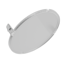
Figure 4 – DMF’s 4-inch downlights utilize microstructure lenses places in front of TIR lenses for final shaping and beam spread.
As fixture dimensions continue shrinking, optical designers increasingly rely on technologies that occupy very little physical space.
Microstructure optical films represent one of the most effective solutions.
These films contain microscopic patterns engineered to redirect, diffuse or homogenize light. Although nearly invisible to the naked eye, these structures can significantly influence beam characteristics.
Placed near the aperture plane, microstructure films often serve as the final stage of beam refinement. They can soften harsh beam edges, eliminate source imaging and create a more uniform luminous appearance.
Their thin profile makes them especially attractive for low-profile fixtures where conventional optics may not fit.
Microstructure films also play an important role in reducing visual distractions such as LED imaging, hotspots and phosphor inconsistencies.
The challenge is that diffusion inherently introduces some efficiency loss. Excessive diffusion can also undo the beam-shaping work performed by upstream optics.
Consequently, successful implementations require a careful balance between beam control, efficiency and visual comfort.
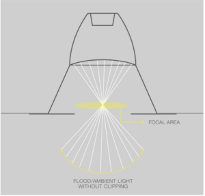
Figure 5- An example of a regressed TIR cross beam optic and the effect on rays of light, utilized in DMF’s 3-inch downlights.
One of the most significant advances in contemporary downlight design is the development of cross beam optical systems.
Cross beam optics seek to solve a common problem in recessed lighting: stray light striking fixture trims and surrounding surfaces.
In traditional systems, some light rays escape at shallow angles and illuminate the trim ring or aperture edge. This creates bright halos around fixtures that draw attention to the luminaire itself.
Cross beam systems redirect those peripheral rays inward, causing them to converge before exiting the fixture.
The benefits are substantial:
Perhaps most importantly, cross beam optics help fixtures visually disappear into the architecture. Rather than becoming bright points on the ceiling plane, they allow attention to remain focused on the illuminated environment itself.
As aperture sizes continue shrinking, cross beam approaches are becoming increasingly important.
Modern optical systems can generally be categorized as either scattering or non-scattering.
Scattering optics deliberately introduce controlled randomness into light paths. Diffusers, frosted lenses and many microstructure films fall into this category.
Their primary advantage is visual smoothness. They soften beams, eliminate hotspots and conceal source details.
However, scattering comes with tradeoffs. Light becomes less predictable, beam edges become less defined and some optical efficiency is inevitably lost.
Non-scattering optics operate differently.
Specular reflectors, polished lenses and precision optical elements preserve ray directionality and redirect light through deterministic optical principles. The resulting beams are highly controlled and efficient.
These systems excel when precise beam shaping, hard cutoffs and maximum intensity concentration are required.
The downside is that non-scattering optics faithfully reproduce source characteristics. Any non-uniformities within the LED source may become visible within the beam pattern.
Most advanced architectural fixtures therefore employ a carefully balanced combination of both approaches.
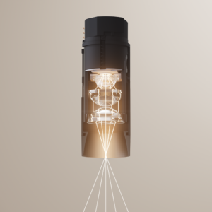
Figure 6 – DMF’s True 1 optical stack and resulting cross beam focus
As the industry continues moving toward apertures of 1 inch and below, optical design will become even more critical.
In these ultra-small formats, every stray ray matters. Even minor amounts of trim illumination can dramatically increase perceived glare. Traditional combinations of reflectors, lenses and diffusion elements often struggle to provide sufficient control within such limited physical space.
This challenge is driving a new generation of optical innovation.
For example, DMF’s True 1 downlight utilizes a patent-pending optical stack that combines multiple non-scattering optical elements with a final microstructure layer. The design creates a true cross beam focus while minimizing spill light and reducing source visibility.
The result is a soft, visually comfortable beam, exceptional glare control and a narrow cutoff angle that would be difficult to achieve using conventional optical approaches alone.
The trend toward smaller apertures shows no signs of slowing. Architects and designers continue to seek cleaner ceilings, more discreet fixtures and lighting systems that quietly complement the built environment.
But miniaturization alone does not create better lighting.
As apertures shrink, optics become increasingly responsible for determining whether a fixture delivers visual comfort or visual distraction. Reflectors, refractive lenses, microstructure films and cross beam technologies all play important roles in shaping the modern lighting experience.
Ultimately, the best small-aperture downlights are not simply miniature fixtures. They are highly engineered optical systems designed to balance efficiency, beam control, glare reduction and occupant comfort.
In the pursuit of visually quiet ceilings, optics have become the true differentiator.
For more in-depth information, read the Recessed LED Optics and Glare Technical Bulletin
|
Optic System |
3 Stage Optical Stack:
Non-Scattering Optical Elements and Microstructure film
Regressed TIR Optic:
Cross Beam Focus and Diffusion Lenses for Beam Softening
Proprietary Folded TIR Optic and Microdiffusion Lenses for Beam Angle Control
|
Light Focus |
Cross Beam
Cross Beam
Traditional Cone
|
Reasons for Use |
– Ultra-small aperture requires the ultimate glare control and minimal spill
-Traditional TIR lenses can’t create a true cross beam focus
– Smaller aperture fixture requires cross beam focus for reduced glare and increased performance
– Diffusion lenses allow for additional beam softening
– Ability to achieve a very shallow optical package
– Wider 4-inch aperture doesn’t require cross beam focus, as the larger aperture is inherently less glare prone